
NOTE: This install includes the additional work for removing an aftermarket vacuum pump relocation bracket.
I need to upgrade my air compressor, and in a major way. I was using the Smittybilt portable, and the amount of time it took to air up four 35″ Duratracs was waaaay too long. My wheeling friends can inflate their tires, have lunch, complete a crossword puzzle book, and read War and Peace by the time I am done.
So, a few weeks ago, I ordered the ARB CKMTA12 Twin compressor from Northridge.
Now, the question arose on where to mount this behemoth compressor. So to answer this, I did what every self-respecting data geek would do; I made a table.

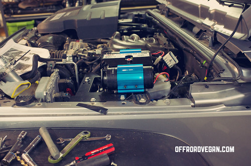
After weighing all the options and their pros and cons, I elected to install the compressor under the hood. I trust ARB’s testing and figure it will survive well being so close to the firewall. I will also be using this mostly with the hood open (tools and tires, no air lockers yet) so the cooling factor is less of a concern.
I ordered the MORE under hood bracket from Northridge.
Once it arrived, I happily skipped out to the garage to start the install, cold beer in hand. I opened the hood, and went to lay out the bracket to ensure it would fit. Houston, we have a problem.
See, I am running the Metal Cloak vacuum pump relocation bracket, as I also have an aftermarket front bumper. Chrysler in their infinite wisdom, decided to place this pump behind the front bumper, so anyone that wants to run an aftermarket bumper, needs to move it.
So understand this write up includes the steps to accommodate the vacuum pump relocation (in progress, come back tonight).
Install Notes:
First and foremost, this install is a real pain. Not so much about the product, but just the fact that there is so little room to work with in the 3.6L pentastar bay. You WILL drop nuts and washers in small places. You WILL squeeze and pinch fingers. Just prepare.
1. Lay out all parts and ensure you have everything needed. The following tools will also come in real handy:
- Flashlight (bright and small)
- Magnetic tool retriever
- Needlenose pliers
- 10mm wrench (small)
- Electrical tape
- Large socket
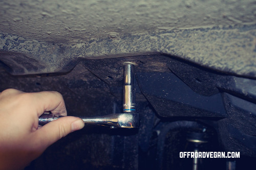
2. Remove the 10mm bolt (shown with socket wrench on it) and also remove the vacuum pump if you have it. MORE instructions claim to remove “bolts” as in plural, but there is only one.

3. Assemble the bracket, spacer, bolts and rods as shown. Ensure the orientation is correct and as shown below. You may not want to fully tighten the “legs” yet.

4. Place the bracket in the engine bay, and orient as shown. Place two small bolts (1/4″) into the two factory holes in plastic housing on DS as seen in the image. Ensure the “legs” seat flush to the plastic below and are level.

5. Once you are certain the fitment is correct, mark off the location of the “legs” and prepare to drill. The MORE instructions provide a couple different options on how to do this, I simply outlined the legs with a screwdriver (my engine bay has some dirt) and drilled pilot holes in the center of these markings. It worked great.
6. Drill the holes. Note in the image below, you can see where I traced the location of the legs.

7. Remove the entire fender “pants” on the driver side by removing the 3 10mm bolts.
8. This is where I departed from the factory instructions. They claim you can see your holes from underneath the Jeep, but I don’t think so. The hole toward the front of the Jeep was totally obscured. So, I ran the bolts up through the plastic (w/locking washer and flat washer per the spec) and into the legs. I did remove the leg from the bracket to do this, and it was easy.
9. With both legs installed, I brought the bracket back into the bay, and reinstalled the legs onto it as in step 3 above.
10. Install the two small bolts into the plastic housing and this time, include the nylock nuts underneath. NOTE: The plastic “piece” I removed the 10mm bolt from has some herculean strength. If you have stubby fingers, you may want to “prop” this up with a socket as I did in this picture. Note, you may slightly bend the rail, as I did but at this point I was getting frustrated and didn’t care.

If you do not go this route, you may need to get creative with getting the nuts into that narrow channel and mounted onto the bolts. See below.

11. With everything installed, tighten all nuts down, and ensure the bracket feels secure.
12. Reinstall fender pants.
13. Install ARB compressor per instructions.
Note: I found it was much easier to remove the engine cover when trying to install the two bolts on the passenger side of the compressor/bracket.
I will post additional details below once the vacuum pump is moved onto this bracket. Stay tuned!
